TELECOM POWER >> Inverters
   SMI3300 Modular Switchmode Inverter
   
Features

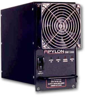
SMI3300 modular inverter system offers new levels of scalability, maintainability, compactness, reliability and performance in a modular inverter package. System growth is easily achieved through the addition of 3.3 kVA SMI3300 inverter modules. System size can be from 3.3 kVA up to 26.4 kVA.

  • SMI3300 inverter modules are “hot swappable” and readily accessible, leading to an extremely low mean time to replace.
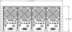
  • The SMI3300 inverter module sets new industry standards 
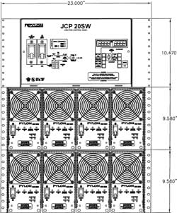
in power density at an amazing 6.4 VA/in3. (A 26.4kVA system including a metering and transfer panel occupies less than 30” (vertically) in a 23” rack.
  • All the advantages of switchmode technology with Pylon reliability built in for continuous duty online operation.
  • Parallelable for increased power or redundancy.
  • Systems may be configured for redundant or non-redundant operation.
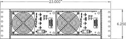
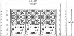
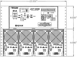
  • 19" (3 modules per cage assembly) or 23" (4 modules per cage assembly) rack mountable cage assemblies (brackets supplied).
  • Low distortion, true sine wave output.
  • Telecom grade input filtering.
  • High efficiency.
  • Short circuit, over/under voltage and thermal protection.
  • Designed to stringent NEBS specifications.
Technical Specifications
Electrical Specs:
Output Waveform: True sine wave, <2.5% THD
Output Power: 3300VA at 0.8 PF; 2750W at 1 PF
Overload Capability: 120% continuous
Load/Line Regulation: 5% combined
Frequency: 60 Hz
Input Voltage: 48VDC nominal; 42-60VDC range
Input Current: 62A nominal at full load & 52 VDC input
Battery Feedback Noise: <30 dBrnC
Efficiency: >87% from 50% to 100% full load
Protection: Reversed DC polarity protection; DC input low-voltage shutdown; output short circuit protection, power limiting and voltage foldback with auto-recovery; magnetic circuit breaker DC input, fan cooling; over-temperature shutdown.
Indicators: Front panel LED's for battery on/reversed polarity, inverter on/fail, load warning (over 80% load)/overload (over 100% load)
Audible Noise: <51 dBA at 1 metre from the unit.
Approvals: FCC Class A subpart 15J compliant, UL & cUL 1778 and NEBS pending
Mechanical Specs:
Operating Temperature: 0 - 55 Degrees Celsius.
Operating Humidity: 0 - 95% (non-condensing).
Operating Altitude: 0 - 10,000 feet maximum before derating.
Dimensions: 9.125” H x 5.125” W x 11.625” D
Weight: 21 lb. (9.5 kg). (per module)
Mounting: "M Series" rackmount cage assembly
Finish: Black matte powder coat.

M Series Cage Assemblies   JCP10SW and JCP20SW Transfer and Alarm Panels

“M Series” Cage Assemblies are available in three versions. The M6.6 is a low-profile unit that holds two SMI modules and mounts in a 23” rack. The M9.9 holds three modules and can be mounted in a 19” or 23” rack. The M13.2 holds four modules and mounts in a 23” rack.

All cage assemblies may be optionally equipped with built-in basic transfer logic and fast “ETS” transfer relay. This configuration provides a very economical and compact solution that includes the capability to transfer to a backup AC source. The transfer logic may be configured to work with one to four inverters in the shelf and for both redundant and non redundant operation.

Larger cage assemblies than initially required may be specified to allow for future growth. Positions in the cage assemblies not occupied by inverters may be covered with blank plates. When it comes time to expand the system, more inverter modules can be easily added.

All DC input, AC in/output and alarm connections to the inverter system are made via rear access terminal blocks.

M6.6 Cage Assembly equipped with two
inverter modules 6.6 kVA / 3.3 kVA redundant
M9.9 Cage Assembly equipped with three inverter modules 9.9 kVA / 6.6 kVA redundant
M13.2 Cage Assembly equipped with four inverter modules 13.2 kVA / 9.9 kVA redundant
 
The optional JCP junction, transfer and metering panels provide comprehensive digital LED metering of voltages and currents, and the intelligence to automatically transfer to a backup AC source based on configurable setpoints.
Metering capabilities include Inverter system output voltage, DC input voltage, AC backup input voltage and output current. The front panel panel also has a mimic diagram with LEDs that indicate the status of all of the major components in the inverter system.

Grouped alarms are provided by the JCP and include major, minor, transfer status and overload alarms. The overload alarm is user adjustable and may be set to trip at any desired system output current level.

The JCP 10SW will interface with a single “M Series” cage assembly while the JCP 20SW provides additional capacity and a junction point that allows two cages to be connected in parallel to increase system capacity.

M13.2 Cage Assembly and JCP 10SW
13.2 kVA / 9.9 kVA redundant with full metering and transfer
Two M13.2 Cage Assemblies with JCP 20SW 26.4 kVA / 23.1 kVA redundant with full metering and transfer

Copyright © 2003 S.D. Electronics